Structural and assembling tests
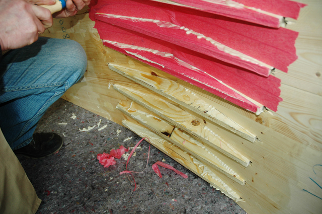
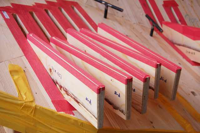
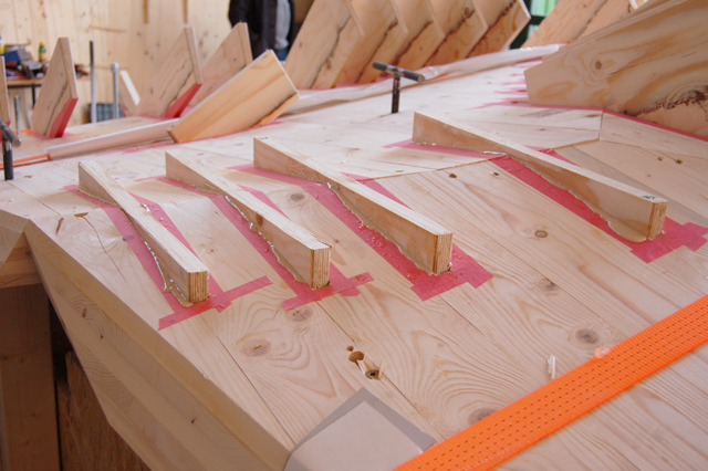
The fabrication of the first series of parts used for the load tests were performed on a 7-axis industrial robot from ABB at Holzcluster Steiermark GmbH in Zeltweg. The second series was produced on a 5-axis CNC machine at Freissling KG, Sebersdorf, Styria.

For parametric support we use a parametric modeller to maintain flexibility of the connector system. This secures the possibility of adapting the system to all possible structural specifications and variations of the initial shape. We use Grasshopper, Rhino-Script and C++ to integrate the data derived from the structural engineers analysis into the geometricalmodel. With reverse engineering we want to optimize our panels following both structural and aesthetical guidelines. For this purpose we “wed” all neighbouring edges of
each panel in the digital model to involve all the parameters defined by the joint geometry and load analysis. In other words all information, like how the panels interact with each other, how many connectors are used and their orientation is stored in the panels as meta data. As a possible joint system we introduce a new system which we call “sewed” joints because of the similarity of the stitch pattern to the stiches of a seam. Currently we perform intensive FEM load analysis which covers self-weight, wind and snow loads which is calculated over all designated panels of the entire structure where we apply the connector system to. In this context of construction we refer to Constructive Parametric Design as an automated support method in the design process [SCHIMEK et al, 2008]. Another aspect which will be taken into account is the management of tolerances of the joints. According to Whitehead who has used tolerance management in the construction of London’s City Hall we will also examine how tolerances will influence our construction system [WHITEHEAD,
2003].


