Assembling the CLT Kerto elements

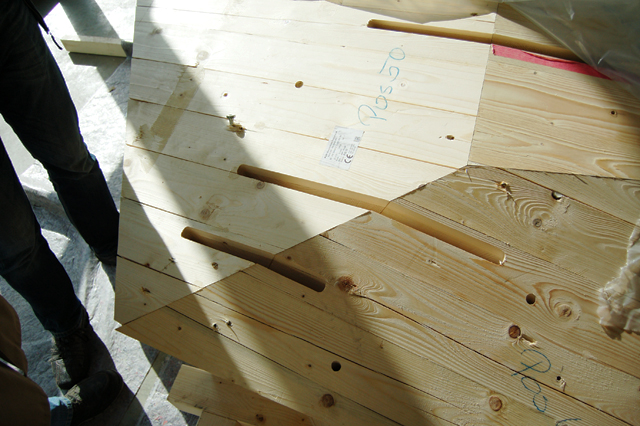
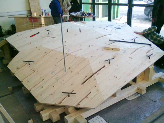
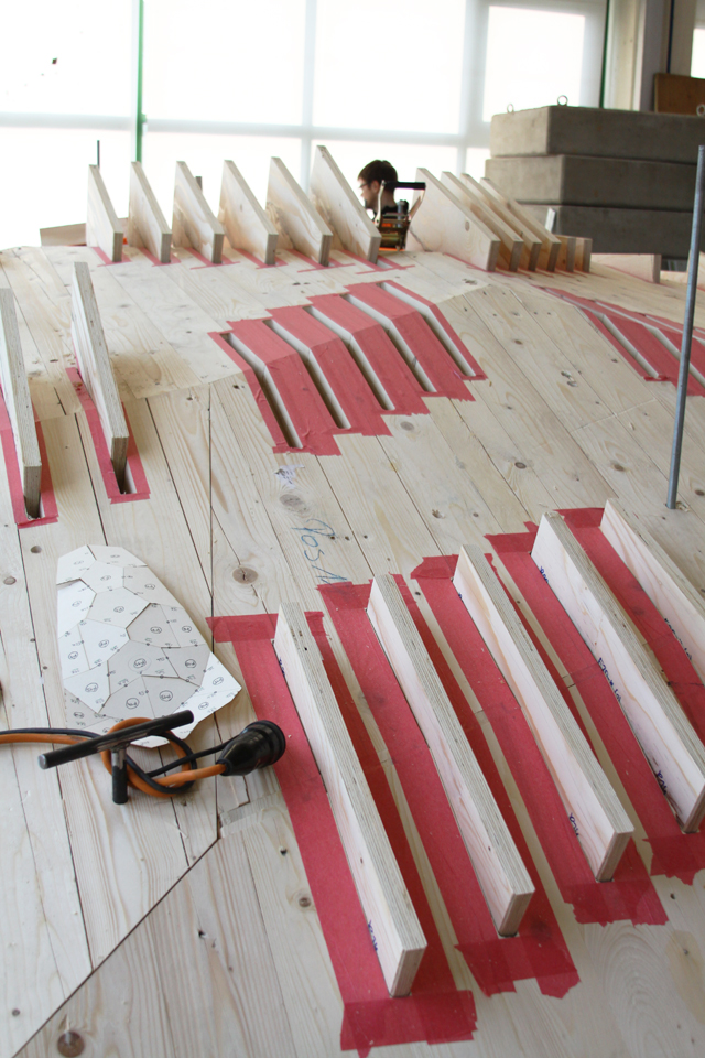
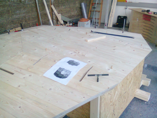
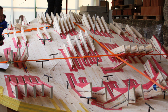
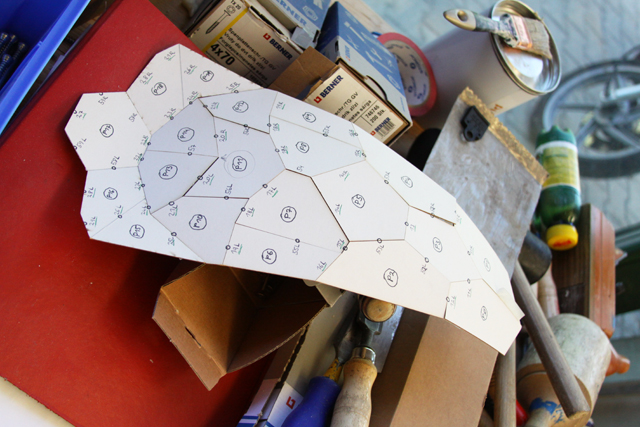
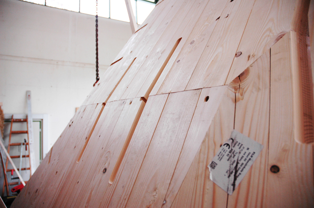
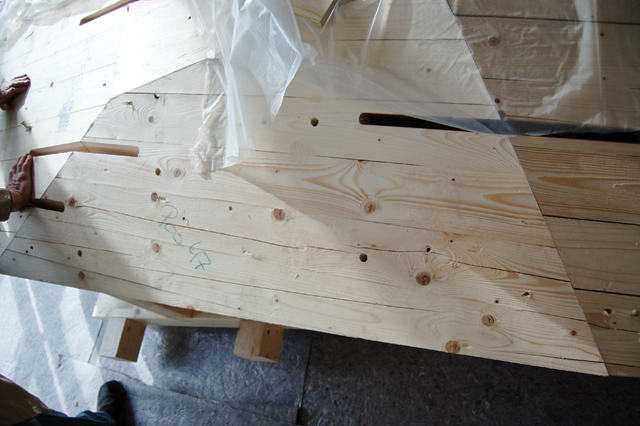
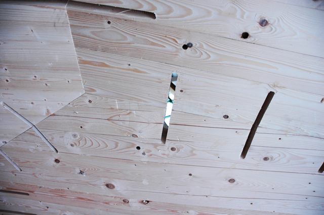
In order to meet the designated requirements of the joints (i.e. aesthetically pleasing higher performance load transmission capacity and easy assembly) in our project, we had to invent a new joint system – the so-called “sewed” joint (figures 10, 11) (schimek et al. 2010). at the moment no such joints for clt- space structures exist (schickhofer et al. 2010). since such space structures are made of cross laminated timber panels or clt, which carry all loads without any additional structure, the joints of the single panels have to transfer both, positive and negative axial forces, lateral forces and bending moments. simultaneously, the joints must be as efficient as possible due to aesthetic and economic reasons. hence, the load-bearing capacity of the joints should not be much lower than the panel’s one. thus, for instance, areas with low stresses get a smaller number of connectors. caused by the anisotropic material behavior of timber, deviations between the grain direction of the outer layer of the clt-panels and the cleats have to be avoided as far as possible. tensile stresses perpendicular to the grain in the panels should be as small as possible (figure 12). With a cnc-machine, slots are cut into the panels in order to glue parallel laminated veneer (cleats made of Kerto-s, which is an engineered timber material with high mechanical load capacity). according to the stresses, the interval of the cleats can be modified.

The tools
In the course of our research we have developed a set of digital tools to integrate the presented approach of free-form surface rationalization into the design process form early design stages on. The implementation of our tool kit can be divided into two components: the core algorithm (the encoded geometrical and mathematical knowledge to perform the discretization of a given surface) and the interface provided to control and refine the panelization process (the actual tools to be used by the designer). We decided to prototypically implement our tools for McNeel’s Rhinoceros Software since “Rhino” is excellent with modeling free-form surfaces and enjoys considerable popularity in the architectural community today. Furthermore, due to the common ground of software development for Rhino and its parametric modelling extension, Grasshopper, we were able to efficiently develop explicit modeling tools for the direct manipulation of geometries, as well as a pure parametric modelling interface to our algorithms- both enabling an inherently different workflow.
